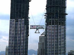
Jambatan Udara Di Menara Berkembar klcc Engineering Design
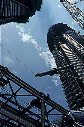
The structural system selected utilises a 'two-hinge arch' springing from supports at level 29 and rising at 63 degrees to support a pair of parallel two-span continuous bridge girders at Level 41.
The structure of the two-level bridge is conventional framing constructed of structural steel with beams moment-connected to columns which bear on the level 41 continuous girders. The bridge is 58.4 m long and weighs about 750 tonnes.
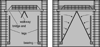
The two-hinge arch supporting the bridge has rotational pins (spherical bearings) at the end of each leg or 'spring point' and at the top or 'crown' of the arch (bearings). The main bridge girders have a rotational (centering) pin directly over the arch crown to permit the crown to rise and fall as the Towers move closer or further apart.
The arch is a centering device, equalising joint movement at both Towers. As the Towers move together or apart, the legs change slope, the spherical bearings rotate at spring points and the legs flex at their top end. The bridge mid-point sinks or rises, flexing the two main girders.
The girders are pinned on the arch crown, which stays centered between the Towers, while both girder and blocks slide on pads. The mid-span centering pin and two girder slip pads accommodate this movement.
Continuous expansion joints provided through the level 42 and 43 structure, facade and roof to each side of the bridge mid point. Providing expansion joints at mid-point reduces the effect of girder flexure on bridge glazing, as window panel movement is then limited to each half-span rather than cumulating over the whole girder length.
When the Towers move side-to-side in opposite directions, or when they 'twist', the arch spring points twist on the spherical bearings and bridge end bearings slide in opposing directions guided by 'sliding keeper' blocks on bridge centreline.
In the event that it loses its arch support, the bridge structure would not collapse but deflect and stay in position.
Assembly of Skybrigde
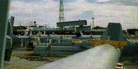
Fabrication
The skybridge was fabricated and shop assembled by Samsung Heavy Industries of South Korea. The fabrication works complied with some of the most stringent industry standards and codes such as those maintained by the American Society for Testing and Materials (ASTM), British Standard (BS), and American Institute of Steel Construction (AISC).
The fully assembled bridge was then dismantled and shipped to Kuala Lumpur in 493 pieces (452.64 tonnes).
To facilitate putting it into place, the skybridge was pre-assembled into five main components comprising the two legs, two end blocks and the centre section.
Centre Section
The 307 parts of the frame for the centre section of the skybridge were fully assembled and bolted. The centre section of the skybridge frame, measuring 41 metres in length, over 5 metres in width and nine metres in height, was assembled at the concourse level.
The centre section's internal floors and roof at level 41, 42 and 43 were constructed in metal decking.
After the roof level concrete slab was placed, the whole assembly was painted and the external building maintenance equipment for the legs installed.
Skybridge Legs
The two inclined legs are approximately 42.6 metres long and weigh about 60 tonnes each.
The five sections of each set of legs were completely assembled and checks on the whole dimension, camber and alignment were made before bolting. Tuned mass dampers have been engineered for the legs.
These dampers have been designed after a complete wind tunnel test to accommodate the comfort level by dampening any effects of unusual wind conditions and possible long term fatigue due to resonance of the legs. These pendulum operated dampers were field tested and inserted to the centre section of the legs just prior to final assembly.
End Blocks
Both end blocks of the skybridge were assembled at concourse level with main girders, cross beams and horizontal bracing. The two end blocks are approximately 8.3 metres long and weigh about 30 tonnes each. After the whole dimension and alignment of the end blocks were checked, they were ready to be lifted.
The skybridge's legs are lifted up one at a time by tower cranes. Once they are in position, control cables are used to lower them over their permanent bearings at level 29.
The two end block girder frames of the skybridge are lifted individually. The blocks are installed about 100mm above their final position at level 41. They are also retracted about 100mm into the tower to provide sufficient clearance for the skybridge centre section during lifting 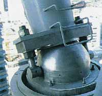
The four lifting jacks located at level 50 of both towers are connected on the bridge centre. The other four lifting jacks located on level 48 of both towers are connected to the bridge ends.
The centre section which weighs 325 tonnes is lifted about 11 metres and restrained. This is to allow the upper 10 metres of the legs to be connected to the girder on the bridge.
After a final check, lifting of the centre section commences.
At a minimum lifting speed of 12 metres per hour, the centre section is gradually lifted to its final level.
Bearings allow bridge legs to flex as the towers move in the wind Steps Seven to Nine took about two weeks. A temporary connection secures together the centre section and the end block girder frame to ensure there is no stress.
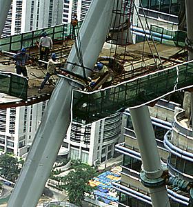
The legs are moved into place. When the legs are in their final position, the skybridge end blocks are lowered on their permanent bearings at Level 41. The centre section is then lowered to meet the legs.
The last phase of the completion of the bridge, with both block ends welded to the towers and legs attached to the box girder beneath the midsection
After the lifting system has been removed, the floors were concreted, the skybridge roofed. The maintenance equipment is set up on stainless steel rails on top of the bridge.
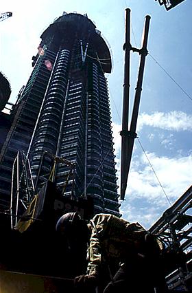
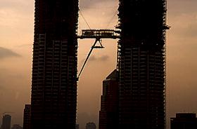
At about 7.40 p.m., on 9 August 1995, after 32 hours of lifting operation, the skybridge was lifted to its final position at the 41st and 42nd levels of the PETRONAS Twin Towers.
|